Angle brackets
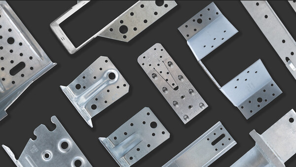
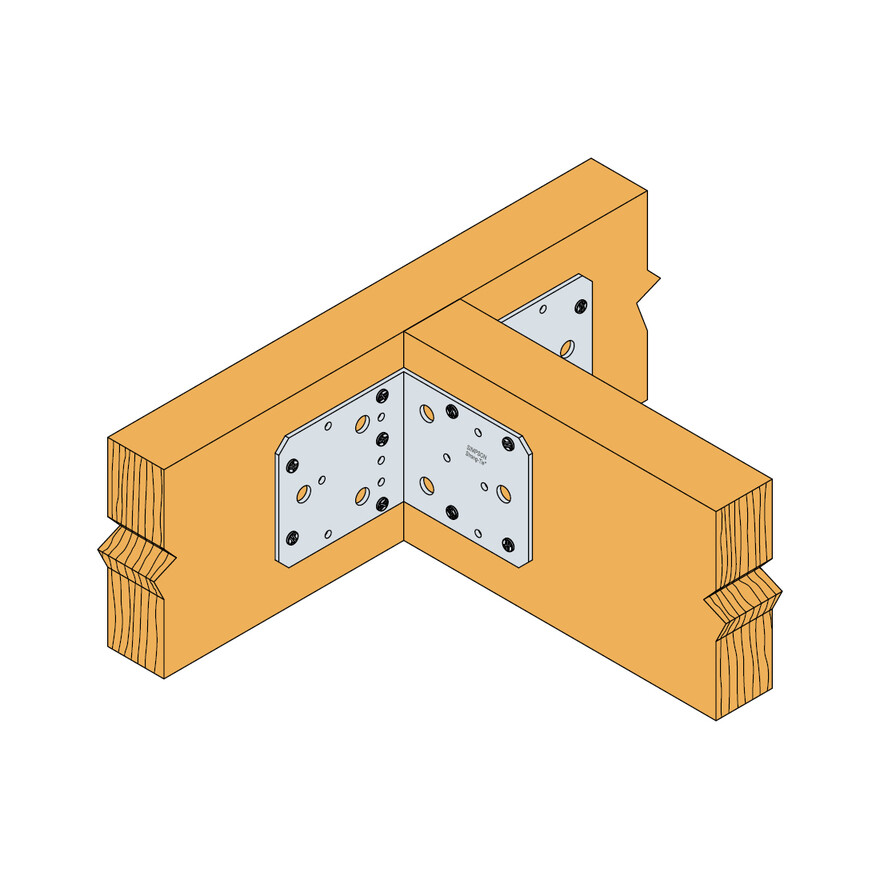
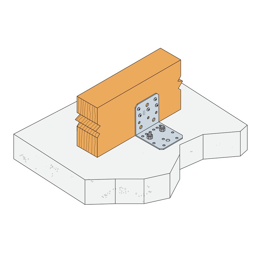
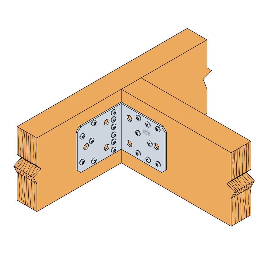
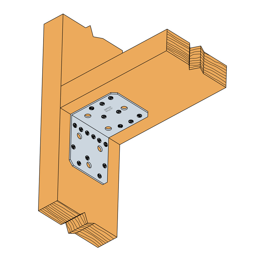
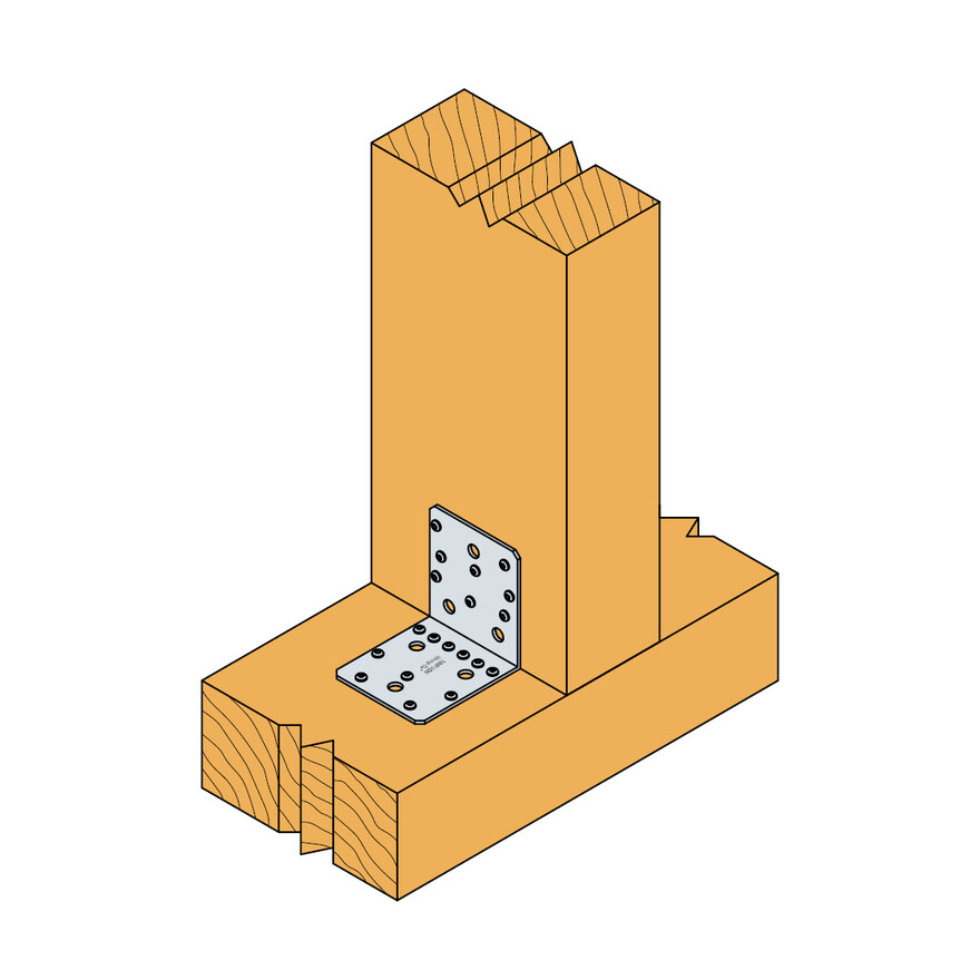
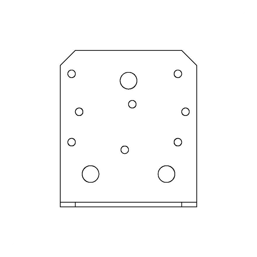
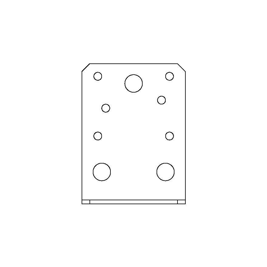
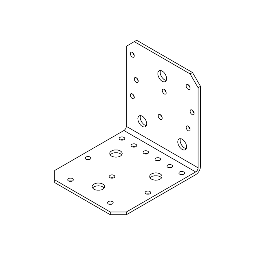
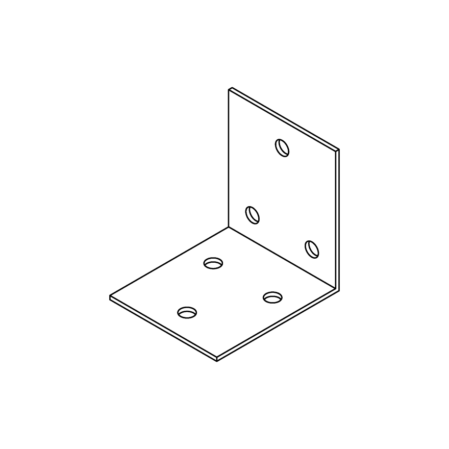
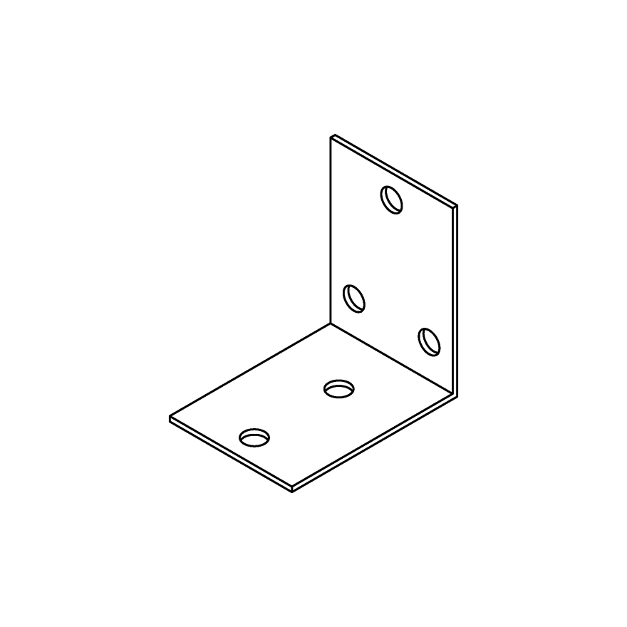
AB angle brackets are used for assemblies in supporting wood construction. The connectors are used in wood-wood assemblies, wood-concrete assemblies, exchanges etc.
Product Details
Features
Material
- Galvanized steel S250GD + Z275 according to NF EN 10346.
Benefits
Angle bracket for supporting constructions
Application
Suitable On
- Supporting member: solid wood, glued-laminated wood, concrete, steel, etc.
- Supported member: solid wood, composite lumber, glued-laminated wood, triangular trusses, profiles, etc.
When to Use
- Fastening of small trusses.
- Cladding plates, cladding uprights.
- Rafter anchors, cantilevers, headers, etc.
Technical Data
Characteristic Values - CLT/Rigid Substrate
| References | Fasteners | Chacteristic Values - CLT/Rigid Substrate [kN] | |||
|---|---|---|---|---|---|
| Flange A | Flange B | R1,k | R2,k = R3,k | ||
| Qty | Qty | Type | CNA4.0x50 | CNA4.0x50 | |
| AB90 | 5 | 2 | M10 | 3 | 3.1 |
| AB105 | 5 | 2 | M10 | 6.2 | 3.2 |
The published characteristic capacity is based on instantaneous load duration and service class 2 according to EC5 (EN 1995) – kmod = 0.9. For other load duration and service class, please refer to the ETA.
Installation
Installation
Fixing
Wood:
- CNA annular ring-shank nails dia. 4.0 x 35 or dia. 4.0 x 50 mm.
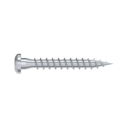
- CSA screws dia. 5.0 x 35 mm or CSA screws dia. 5.0 x 40 mm.
- Bolts.
- LAG screws.
Concrete:
Concrete substrate
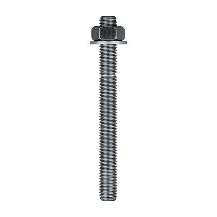
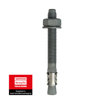
- Mechanical anchor: WA M10-78/5 OR WA M12-104/5 pin.
- Chemical anchor: AT-HP resin + LMAS M10-120/25 or LMAS M12-150/35 threaded rod.
Hollow masonry substrate:
- Chemical anchor: AT-HP or POLY-GP resin + LMAS M12-150/35 threaded rod + SH M16-130 screen.
On steel:
- Bolts.
Technical information
F1: tensile force in the central axis of the angle-bracket
Particular situation of a fastening with only one angle-bracket:
- If the overall structure prevents the rotation of the purlin or the post, the tensile strength is equal to half of the given value for two angle-brackets.
- Otherwise, the connection resistance depends on the « f » distance between the vertical contact surface and the point of load application.
F2 and F3: shear lateral force
Particular situation of a connection with only one angle-bracket:
- The resistance value to consider is equal to half of the one given for two angle-brackets.
F4 and F5: transversal force directed towards or opposite the angle-bracket
- The connection resistance depends on the « e » distance between the base of the angle-bracket and the point of load application.
- To consult corresponding loads, contact us.
Only F1, F2 and F3 forces for connections with 2 angle-brackets are present on this sheet.
For more information, contact us.
