Bypass Framing Fixed Clip Connector
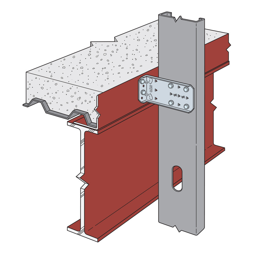
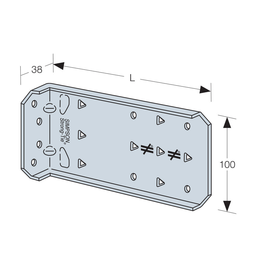
The FCB clip is an economical, high performance fixed clip connector that can be used for a variety of framing applications. It is rated for tension, compression and shear loads. It also allows the designer the flexibilty to specify different screw and anchorage patterns to conform to desired load levels.
Technical Data
Product Dimensions
| References | Dimensions [mm] | Holes | |||||
|---|---|---|---|---|---|---|---|
| A | B | C | t | Flange A | Flange B | ||
| Ø5.5 | Ø4.8 | Tri | |||||
| FCB43.5-R25 | 38 | 89 | 100 | 1.6 | 4 | 4 | 2 |
| FCB45.5-R25 | 38 | 140 | 100 | 1.6 | 4 | 4 | 5 |
| FCB47.5-R25 | 38 | 191 | 100 | 1.6 | 4 | 4 | 8 |
| FCB49.5-R25 | 38 | 241 | 100 | 1.6 | 4 | 4 | 8 |
| FCB411.5-R25 | 38 | 292 | 100 | 1.6 | 4 | 4 | 8 |
Performance - FCB to Stud (Min. Fasteners)
| References | Fasteners | Safe Working Loads [kN] | Characteristic Capacities [kN] | ||||||||||||||
|---|---|---|---|---|---|---|---|---|---|---|---|---|---|---|---|---|---|
| Flange B | Member Thickness [mm] | Member Thickness [mm] | |||||||||||||||
| Self Drilling Screw (X1B1214) | 1.2 | 1.6 | 1.2 | 1.6 | |||||||||||||
| R1 | R2 | R3 | R4 | R1 | R2 | R3 | R4 | R1 | R2 | R3 | R4 | R1 | R2 | R3 | R4 | ||
| FCB43.5-R25 | 4 | 0.9 | 4.9 | 4.3 | 5 | 1.5 | 5.6 | 4.3 | 6.6 | 1.5 | 7.9 | 6.9 | 8 | 2.5 | 8.9 | 6.9 | 10.6 |
| FCB45.5-R25 | 4 | 0.8 | 4.9 | 4.3 | 4.2 | 1.5 | 4.9 | 4.3 | 5.9 | 1.3 | 7.9 | 6.9 | 6.7 | 2.5 | 7.9 | 6.9 | 9.4 |
| FCB47.5-R25 | 4 | 0.6 | 4.9 | 4.2 | 1.5 | 1.2 | 4.9 | 4.2 | 1.6 | 1 | 7.9 | 6.7 | 2.3 | 2.9 | 7.9 | 6.7 | 2.6 |
| FCB49.5-R25 | 4 | 0.5 | 4.9 | 4.2 | 1.1 | 0.5 | 4.9 | 4.2 | 1.6 | 0.8 | 7.9 | 6.7 | 1.8 | 0.8 | 7.9 | 6.7 | 2.6 |
| FCB411.5-R25 | 4 | 0.4 | 4.9 | 4.1 | 0.9 | 0.4 | 4.9 | 4.1 | 1.6 | 0.6 | 7.9 | 6.5 | 1.5 | 0.6 | 7.9 | 6.5 | 2.6 |
1. Min. fastener quantity and load values - fill all round holes
2. Loads are based on clip capacity only and do not considwer anchorage. the capacity of the system will be the minimum of the tabluated value and the FCB Anchorage Loads
Performance - FCB to Stud (Max. Fasteners)
| References | Fasteners | Safe Working Load [kN] | Characteristic Capacity [kN] | ||||||||||||||
|---|---|---|---|---|---|---|---|---|---|---|---|---|---|---|---|---|---|
| Flange B | Member Thickness [mm] | Member Thickness [mm] | |||||||||||||||
| Self Drilling Screw (X1B1214) | 1.2 | 1.6 | 1.2 | 1.6 | |||||||||||||
| R1 | R2 | R3 | R4 | R1 | R2 | R3 | R4 | R1 | R2 | R3 | R4 | R1 | R2 | R3 | R4 | ||
| FCB43.5-R25 | - | 1.2 | 4.9 | 5.6 | 6.5 | 1.5 | 5.6 | 7.7 | 8.5 | 1.9 | 7.9 | 9 | 10.4 | 2.5 | 8.9 | 12.3 | 13.6 |
| FCB45.5-R25 | - | 0.9 | 4.9 | 5.6 | 6.6 | 1.5 | 4.9 | 7.7 | 8.6 | 1.5 | 7.9 | 9 | 10.6 | 2.5 | 7.9 | 12.3 | 13.7 |
| FCB47.5-R25 | - | 1.2 | 4.9 | 5.6 | 4.7 | 1.5 | 4.9 | 7.7 | 6.4 | 1.9 | 7.9 | 9 | 7.5 | 2.5 | 7.9 | 12.3 | 10.3 |
| FCB49.5-R25 | - | 1.2 | 4.9 | 5.6 | 5 | 1.5 | 4.9 | 7.7 | 5.3 | 1.9 | 7.9 | 9 | 7.9 | 2.5 | 7.9 | 12.3 | 8.5 |
| FCB411.5-R25 | - | 1.2 | 4.9 | 5.6 | 3.8 | 1.5 | 4.9 | 7.7 | 3.8 | 1.9 | 7.9 | 9 | 6.1 | 2.5 | 7.9 | 12.3 | 6.1 |
1. Max. fastener quantity and load values - fill all round holes & triangular holes
2. Loads are based on clip capacity only and do not considwer anchorage. the capacity of the system will be the minimum of the tabluated value and the FCB Anchorage Loads
Anchorage Values - FCB to Structure
| References | Safe Working Anchorage Loads [kN] | Characteristic Anchorage Loads [kN] | ||||||||||||||||
|---|---|---|---|---|---|---|---|---|---|---|---|---|---|---|---|---|---|---|
| R2,SWL = R3,SWL | R4,SWL | R2,k = R3,k | R4,k | |||||||||||||||
| FCB43.5 | FCB45.5 | FCB47.5 | FCB49.5 | FCB411.5 | FCB43.5 | FCB45.5 | FCB47.5 | FCB49.5 | FCB411.5 | |||||||||
| Min/Max | Min/Max | Min | Max | Min | Max | Min | Max | Min/Max | Min/Max | Min | Max | Min | Max | Min | Max | |||
| 2# Self Drilling Screw (XLQ114B1224) | 5 | 2.8 | 1.8 | 1.1 | 2 | 0.8 | 1.2 | 0.5 | 0.8 | 7.9 | 4.4 | 2.9 | 1.8 | 3.2 | 1.3 | 1.9 | 0.9 | 1.4 |
| 3# Self Drilling Screw (XLQ114B1224) | 7.3 | 3.1 | 2 | 1.2 | 2.2 | 0.9 | 1.3 | 0.6 | 0.9 | 11.7 | 4.9 | 3.2 | 2 | 3.5 | 1.4 | 2.1 | 1 | 1.5 |
| 4# Self Drilling Screw (XLQ114B1224) | 9.9 | 5.6 | 3.6 | 1.6 | 3 | 1.6 | 2.4 | 1.2 | 1.7 | 15.9 | 8.9 | 5.8 | 2.6 | 6.3 | 2.5 | 3.8 | 2 | 2.7 |
| 2# C20 Concrete Screw (TTN215134H) | 1.7 | 1.8 | 1.4 | 0.9 | 1.4 | 0.9 | 0.9 | 0.6 | 0.7 | 2.7 | 3 | 2.2 | 1.4 | 2.2 | 1 | 1.5 | 1 | 1.1 |
| 3# C20 Concrete Screw (TTN215134H) | 2.3 | 2.1 | 2.1 | 1.3 | 2.1 | 1.3 | 1.4 | 0.9 | 1 | 3.7 | 3.3 | 3.3 | 2.1 | 3.3 | 1.5 | 2.2 | 1.5 | 1.6 |
| 4# C20 Concrete Screw (TTN215134H) | 3 | 2.9 | 2.8 | 1.7 | 2.8 | 1.7 | 1.8 | 1.2 | 1.3 | 4.8 | 4.6 | 4.5 | 2.8 | 4.5 | 2 | 2.9 | 2 | 2.1 |
