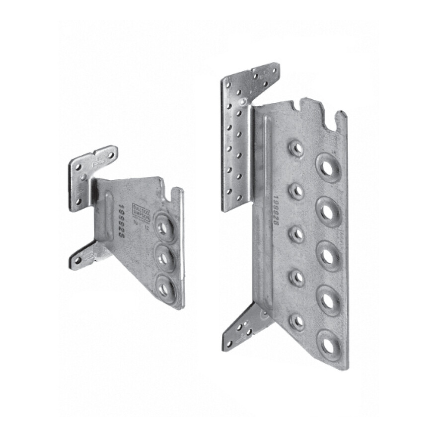
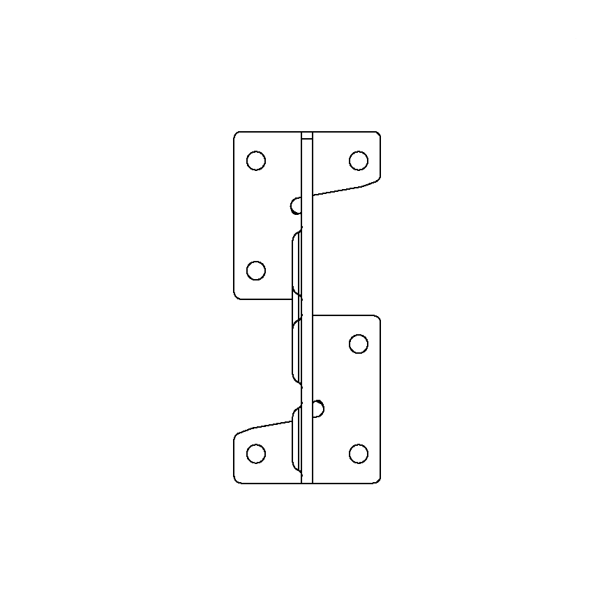
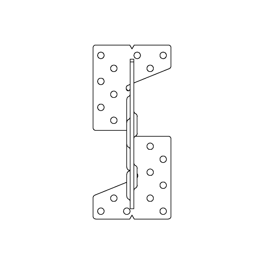
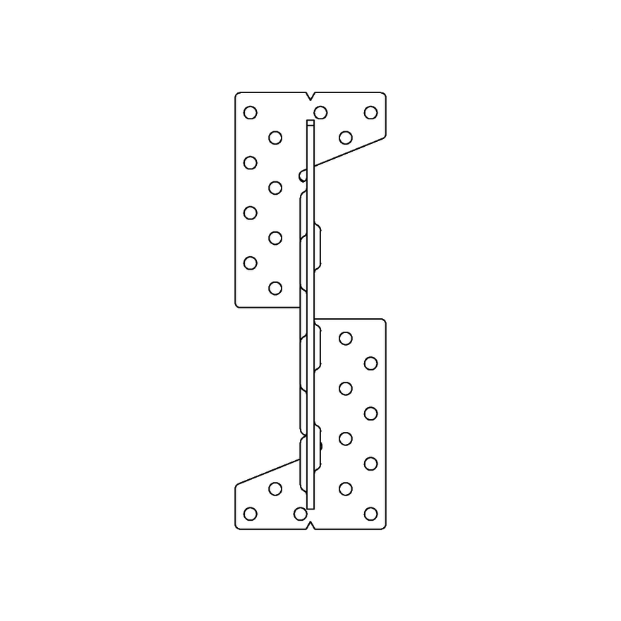
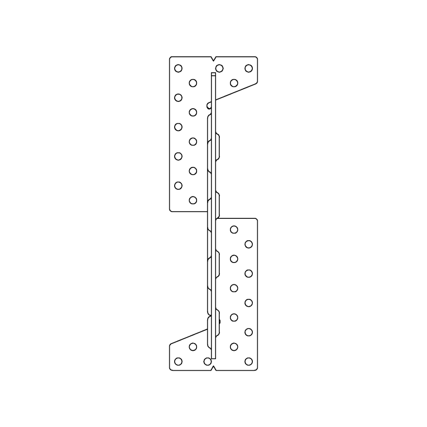
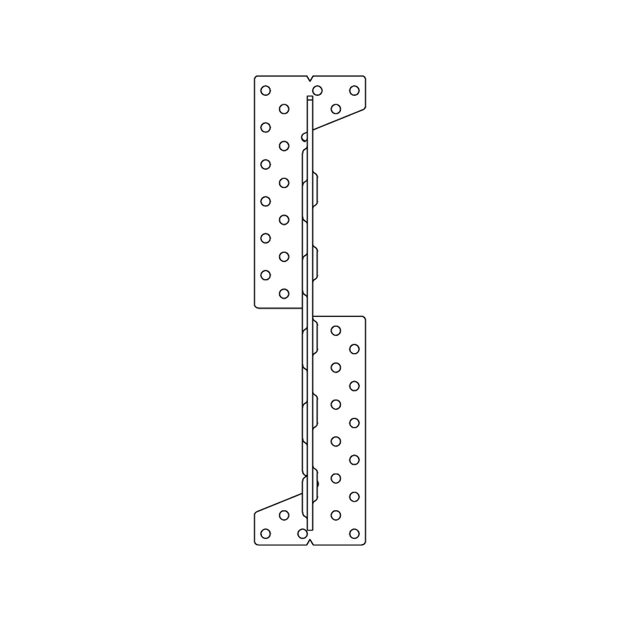
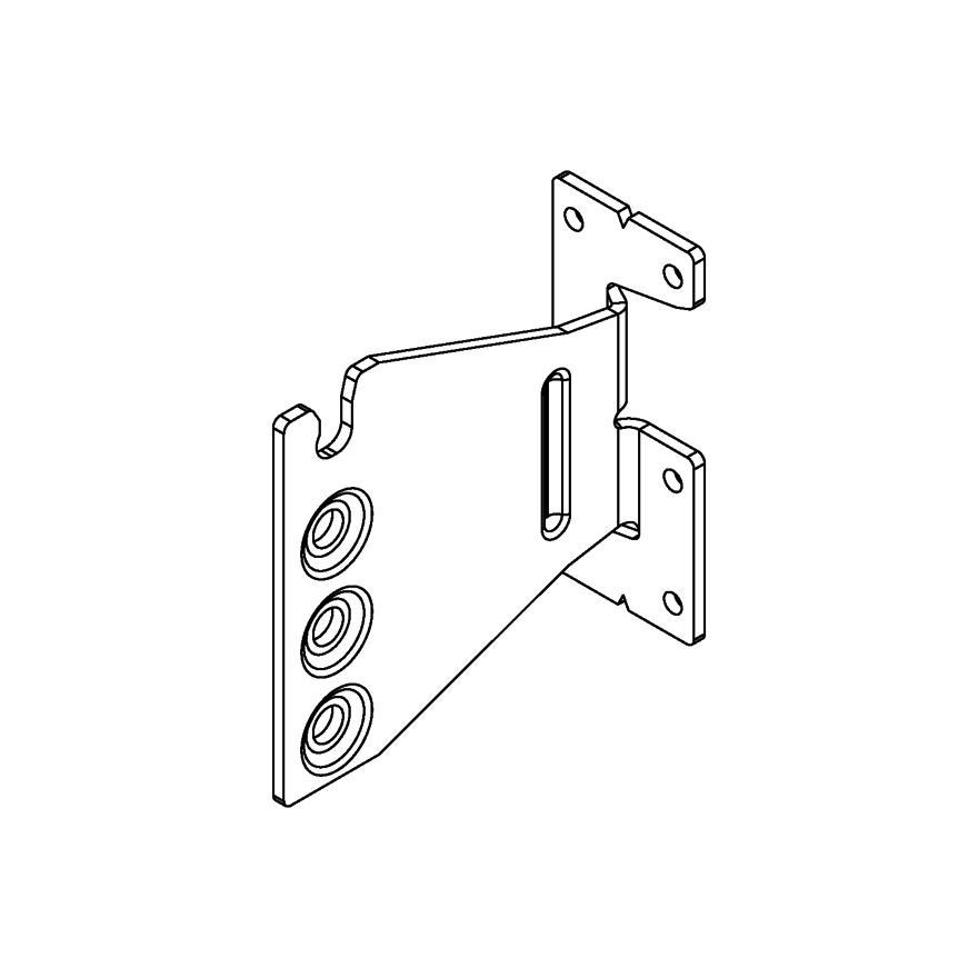
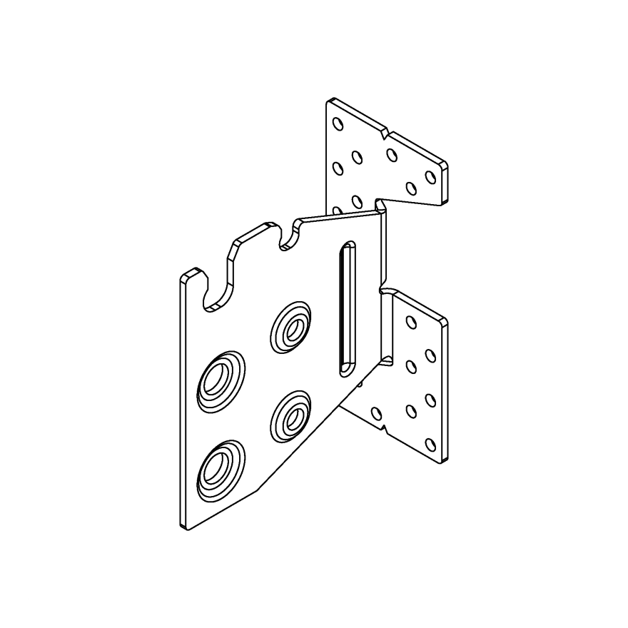
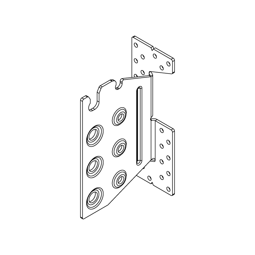
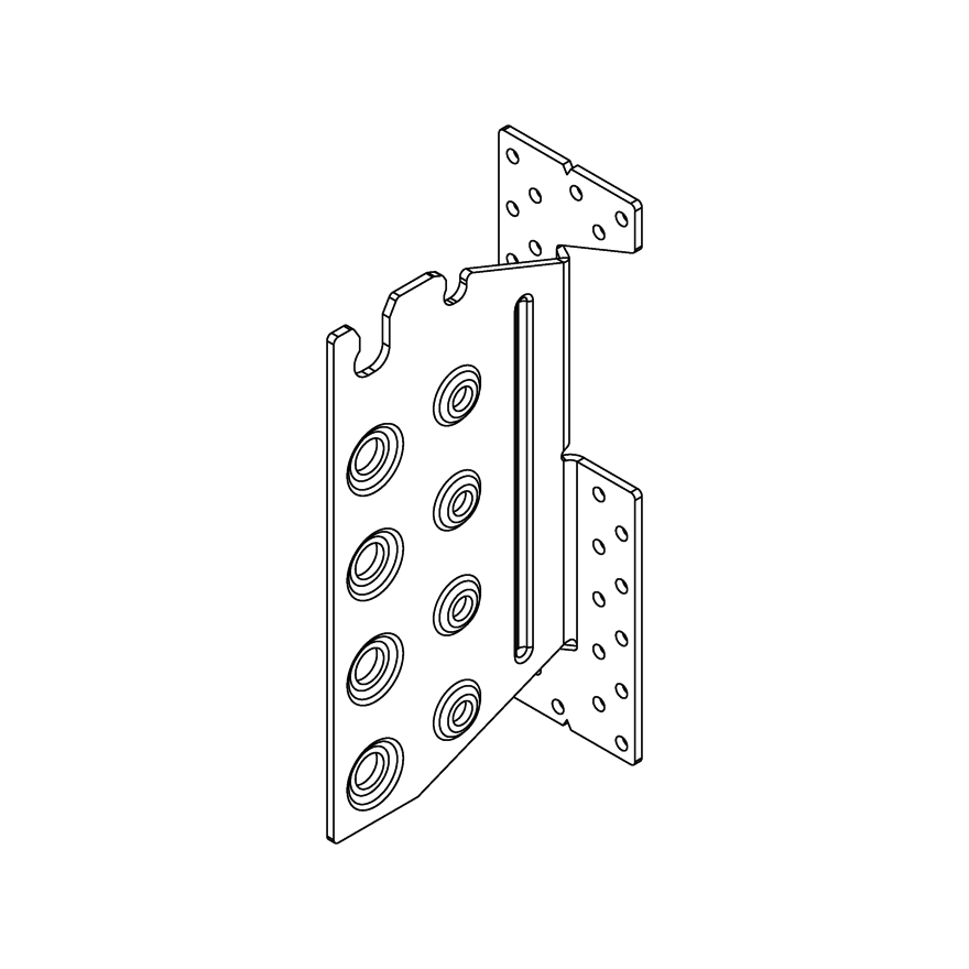
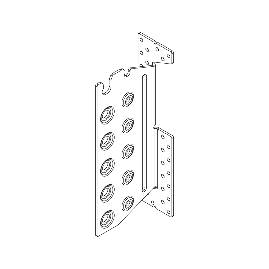
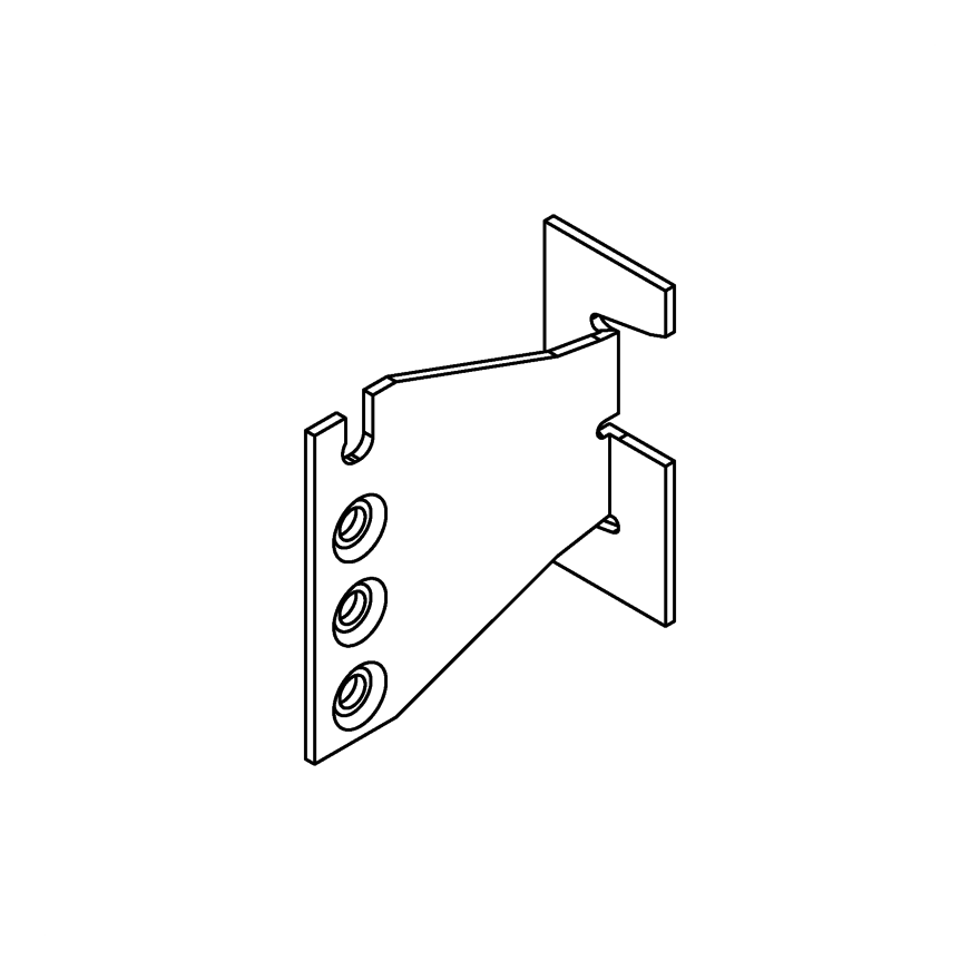
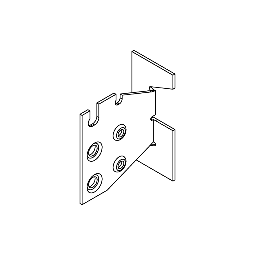
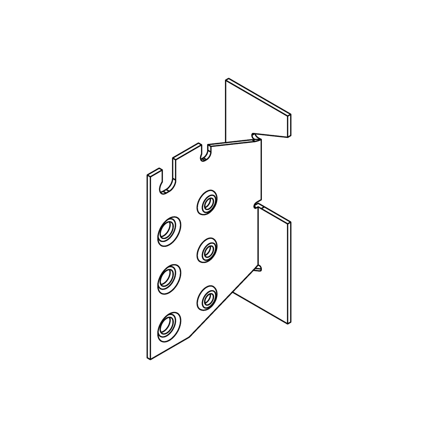
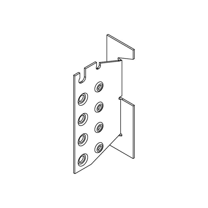
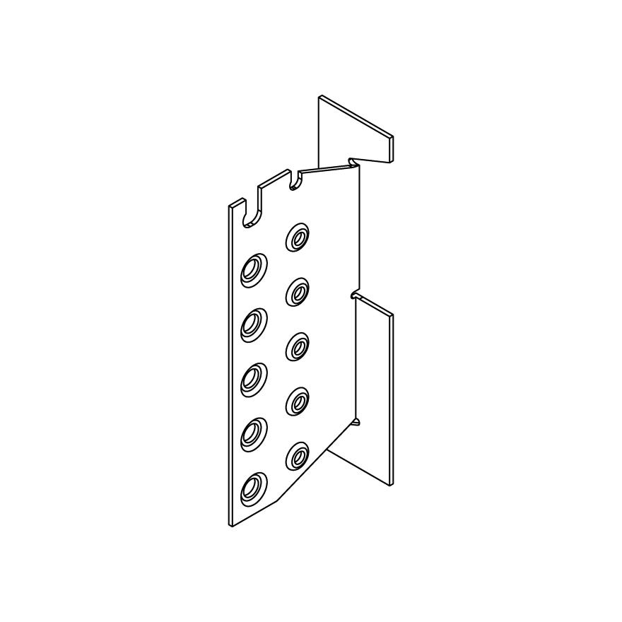
Concealed Beam Hanger
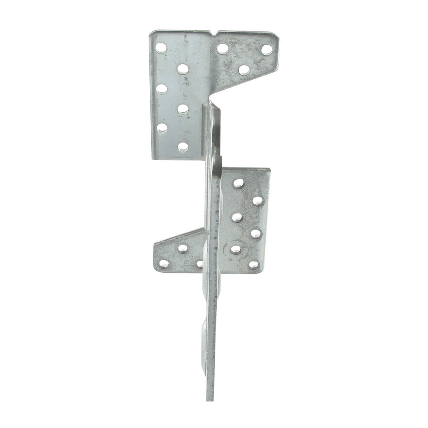
The TU galvanised steel, load rated hanger provides an aesthetically attractive
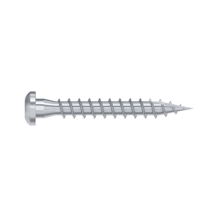
connection for exposed beams. Mild steel dowels and screws are included.
Product Details
Features
Material
- Steel S250GD + Z275 according to NF EN 10346
- Thickness 3 mm
- Half-hour fire resistance subject to a special installation
Benefits
Invisible assembly
Timber to Timber applications
Optimized implementation complies with Eurocodes
Application
Header member
- Supporting member: solid wood, glued-laminated wood, composite lumber
- Supported member: solid wood, glued-laminated wood, composite lumber
For Use With
- Joists
- Purlins
- Supporting beam
Technical Data
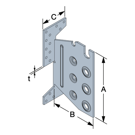
Product Dimensions
| References | Joist Size [mm] | Product Dimensions [mm] | Header holes | Joist holes | ||||||||
|---|---|---|---|---|---|---|---|---|---|---|---|---|
| Width | Height | A | B | C | t | Ø5 | Ø8,5 | Ø12,5 | ||||
| Min | Max. | Min β=0 | Min β≠0 | Max. | ||||||||
| TU12 | 45 | 120 | 120 | 160 | 200 | 96 | 97.5 | 40 | 3 | 6 | 4 | - |
| TU16 | 60 | 160 | 160 | 190 | 240 | 134 | 104.5 | 60 | 3 | 18 | - | 3 |
| TU20 | 60 | 160 | 200 | 225 | 280 | 174 | 104.5 | 60 | 3 | 22 | - | 4 |
| TU24 | 60 | 160 | 240 | 260 | 300 | 214 | 104.5 | 60 | 3 | 26 | - | 5 |
| TU28 | 60 | 160 | 280 | 295 | 340 | 254 | 104.5 | 60 | 3 | 30 | - | 6 |
Product Capacities
| References | Product Capacities - Slope = 0, Skew = 0 | ||||||||||||||||||
|---|---|---|---|---|---|---|---|---|---|---|---|---|---|---|---|---|---|---|---|
| Number of Fasteners | Product characteristic capacities - Timber C24 [kN] | ||||||||||||||||||
| Header | Joist | R1,k | R2,k | R3,k | |||||||||||||||
| Qty | Type | Qty | Type | Dowels length [mm] | Dowels length [mm] | Dowels length [mm] | |||||||||||||
| 45 | 60 | 80 | 100 | 120 | 45 | 60 | 80 | 100 | 120 | 45 | 60 | 80 | 100 | 120 | |||||
| TU12 | 6 | CSA5,0x40 | 4 | STD8 | 7.6 | 8.1 | 9 | 10.1 | 10.7 | 5.7 | 6.1 | 6.8 | 7.6 | 8 | 0.9 | 1.1 | 1.6 | 2.1 | 2.7 |
| TU16 | 18 | CSA5,0x40 | 3 | STD12 | - | 17.5 | 18.1 | 19.2 | 20.5 | - | 11.7 | 12.1 | 12.8 | 13.7 | - | 1.5 | 2.1 | 2.8 | 3.6 |
| TU20 | 22 | CSA5,0x40 | 4 | STD12 | - | 26.7 | 27.6 | 29.2 | 31.1 | - | 20 | 20.7 | 21.9 | 23.3 | - | 2 | 2.8 | 3.7 | 4.5 |
| TU24 | 26 | CSA5,0x40 | 5 | STD12 | - | 36.6 | 37.7 | 39.8 | 42.5 | - | 29.3 | 30.2 | 31.8 | 34 | - | 2.5 | 3.5 | 4.4 | 5.6 |
| TU28 | 30 | CSA5,0x40 | 6 | STD12 | - | 46.9 | 48.3 | 50.9 | 54.1 | - | 39.1 | 40.3 | 42.4 | 45.1 | - | 2.9 | 4.1 | 5.3 | 6.5 |
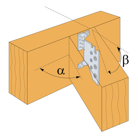
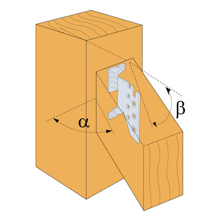
Characteristic Capacities - Sloped Installation (Slope upto 45°, Skew = 0°)
| References | Characteristic Capacities - Sloped Installation (Slope upto 45°, Skew = 0°) | ||||||||||||||||||
|---|---|---|---|---|---|---|---|---|---|---|---|---|---|---|---|---|---|---|---|
| Number of Fasteners | Product characteristic capacities - Timber C24 [kN] | ||||||||||||||||||
| Header | Joist | R1,k - Slope β=15° | R1,k - Slope β=30° | R1,k - Slope β=45° | |||||||||||||||
| Qty | Type | Qty | Type | Dowels length [mm] | Dowels length [mm] | Dowels length [mm] | |||||||||||||
| 45 | 60 | 80 | 100 | 120 | 45 | 60 | 80 | 100 | 120 | 45 | 60 | 80 | 100 | 120 | |||||
| TU12 | 6 | CSA5,0x40 | 4 | STD8 | 7.6 | 8.1 | 9 | 10.1 | 10.7 | 7.6 | 8.1 | 9 | 10.1 | 10.7 | 7.6 | 8.1 | 9 | 10.1 | 10.7 |
| TU16 | 18 | CSA5,0x40 | 3 | STD12 | - | 16.9 | 17.4 | 18.3 | 19.4 | - | 16.5 | 16.8 | 17.5 | 18.5 | - | 15.9 | 16.4 | 17 | 17.9 |
| TU20 | 22 | CSA5,0x40 | 4 | STD12 | - | 25.8 | 26.4 | 27.8 | 29.5 | - | 25.1 | 25.6 | 26.7 | 28.1 | - | 24.4 | 25.1 | 26.1 | 27.4 |
| TU24 | 26 | CSA5,0x40 | 5 | STD12 | - | 35.4 | 36.2 | 38 | 40.2 | - | 34.3 | 35.2 | 36.6 | 38.6 | - | 33.6 | 34.7 | 36 | 37.8 |
| TU28 | 30 | CSA5,0x40 | 6 | STD12 | - | 45.5 | 46.4 | 48.6 | 51.4 | - | 44 | 45.3 | 47.1 | 49.5 | - | 43.4 | 44.9 | 46.5 | 48.7 |
Skewed Only: Skewed & Sloped Installation - Skew upto 60°, Slope upto 45°
| References | Skewed Only: Skewed & Sloped Installation - Skew upto 60°, Slope upto 45° | |||||||||||||||||||||||
|---|---|---|---|---|---|---|---|---|---|---|---|---|---|---|---|---|---|---|---|---|---|---|---|---|
| Number of Fasteners | Product characteristic capacities - Timber C24 [kN] | |||||||||||||||||||||||
| Header | Joist | R1,k - Slope β=0° | R1,k - Slope β=15° | R1,k - Slope β=30° | R1,k - Slope β=45° | |||||||||||||||||||
| Qty | Type | Qty | Type | Dowel Lengths | Dowels length [mm] | Dowels length [mm] | Dowels length [mm] | |||||||||||||||||
| 45 | 60 | 80 | 100 | 120 | 45 | 60 | 80 | 100 | 120 | 45 | 60 | 80 | 100 | 120 | 45 | 60 | 80 | 100 | 120 | |||||
| TU12 | 6 | CNA4,0x50 | 4 | STD8 | 7 | 7.4 | 8.2 | 9.1 | 9.6 | 6.8 | 7.2 | 7.9 | 8.7 | 9.3 | 6.6 | 6.9 | 7.5 | 8.2 | 9 | 6.4 | 6.6 | 7.1 | 7.8 | 8.5 |
| TU16 | 14 | CNA4,0x50 | 3 | STD12 | - | 16.4 | 16.9 | 17.8 | 19 | - | 15.9 | 16.3 | 17.1 | 18.1 | - | 15.4 | 15.7 | 16.4 | 17.2 | - | 15 | 15.4 | 15.9 | 16.7 |
| TU20 | 14 | CNA4,0x50 | 4 | STD12 | - | 25 | 25.8 | 27.2 | 28.9 | - | 24.2 | 24.8 | 25.9 | 27.4 | - | 23.6 | 24 | 25 | 26.2 | - | 22.9 | 23.5 | 24.4 | 25.5 |
| TU24 | 18 | CNA4,0x50 | 5 | STD12 | - | 34.4 | 35.4 | 37.3 | 39.5 | - | 33.3 | 34.1 | 35.6 | 37.6 | - | 32.4 | 33.1 | 34.4 | 36.1 | - | 31.6 | 32.6 | 33.7 | 35.2 |
| TU28 | 18 | CNA4,0x50 | 6 | STD12 | - | 44.3 | 45.5 | 47.8 | 50.6 | - | 43 | 43.8 | 45.8 | 48.2 | - | 41.7 | 42.7 | 44.3 | 46.5 | - | 40.9 | 42.2 | 43.7 | 45.6 |
Rotational Installation
| References | Rotated Installation | |||||||
|---|---|---|---|---|---|---|---|---|
| Fasteners | Joist | Characteristic Capacities - Timber C24 | ||||||
| Header | Qty | Dowel | Dowel Lengths [mm] | |||||
| Qty | Type | 60 | 80 | 100 | 120 | |||
| TU12 | 6 | CSA5.0x40 | 4 | STD8 | 1.5 | 2 | 2.5 | 3 |
| TU16 | 18 | CSA5.0x40 | 3 | STD12 | 2 | 2.6 | 3.3 | 4 |
| TU20 | 22 | CSA5.0x40 | 4 | STD12 | 2.7 | 3.5 | 4.4 | 5.1 |
| TU24 | 26 | CSA5.0x40 | 5 | STD12 | 3.4 | 4.4 | 5.3 | 6.4 |
| TU28 | 30 | CSA5.0x40 | 6 | STD12 | 4.3 | 5.3 | 6.4 | 7.7 |
Installation
Installation
Fixing
On supporting wood member: TU/TUB/TUBS
- CNA annular ring-shank nails dia. 4.0 x 50 mm or CSA screws dia. 5.0 x 40 mm
- Lag screws and bolts dia. 10 mm only for TUB/TUBS
On supported member: Steel dowel S235JR type STD12
- TU12: dia. 8 mm type STD 8
- TU16 to 28: dia. 12 mm type STD 12
- TUB/TUBS: dia. 12 mm type STD 12
The length of the dowels is less than or equal to the width of the supported joist.
TU: wood/wood fastening only with nails/screws
TUB: wood/wood fastening only with nails/screws or lag screws
TUBS: wood/wood fastening only with nails/screws or lag screws
Concrete and steel substrate:
It is not recommended to use hangers on concrete or steel substrate as the size of the bolts makes the distance from the edge of the wood to the dowels non-compliant with Eurocode 5.
Installation
• Dowels aligned across the grain may cause splitting if the wood shrinks excessively. Use only in glulam, composite timber or well dried timber. Verify
that the header can take the required fasteners specified in the table.
• Attach to the supporting beam with CSA 5.0 x 40mm screws (supplied).
• Specify dowel length and TU size to fit the application.
• Preparation of carried beam is best done off-site with cutting and boring
tools.
• Holes in beam should be same diameter as dowel to ensure tight fit.
• Centre the TU within height of carried beam.
• Centre dowels within the width of the carried member.
• For a sloped installation the TU hanger remains as standard and the timber
is cut and angled to suit the slope.
• Recommended for internal dry environments (service class 1 & 2) only.
Installation Procedure for a TU Concealed Connector:
ATTACH CONNECTOR TO HEADER
• Position the connector at the pre-determined height and screw the connector to the header or post.
• Fill all holes with screws supplied.
PREPARE THE BEAM
• Cut the beam to the length specified.
• Cut a slot into the end of the beam. Slot width for TU12 is 6mm and 9mm for all other sizes.
• Cut the slot 3mm deeper than the TU and short of the beam height for concealed
installation. This allows the connector to be hidden from below. Otherwise cut the slot 3mm deeper than the TU and through the entire beam height.
• Fully concealed only: Rout a pocket into the beam end. The pocket should be 6mm deep, enough to hide the thickness of the TU and the screw heads. This eliminates the gap between the beam & header (see Pocket Concealed installation example below).
DRILL BEAM DOWEL HOLES
• Using the TU as a template, mark the hole positions, remove the TU and drill the holes.
• Drill the dowel holes to the required diameter. Dowel hole diameter for the TU12 is 8mm and 12mm for all other sizes.
INSTALL BEAMS
• Install top dowel into the carried beam first. Slip beam into place and install the remaining dowels working from the top downwards.
• Fully concealed only: To hide exposed dowel holes when the installation is complete, glue and plug the holes.
