Light Gauge Steel Splicing Clip
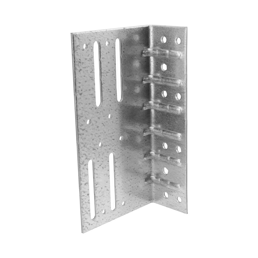
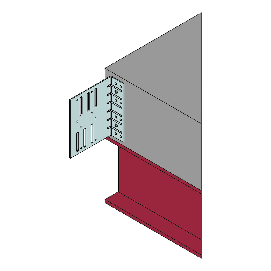
The LGSSC is a Universal Oversail Splice Bracket designed to connect light gauge steel studs to the primary structure in continuous walling installations.
The LGSSC provides a secure connection to the floor slab whilst allowing for up to 50mm of vertical adjustment between butt jointed light gauge steel studs.
Product Details
Features
Features
- Suitable for use on oncrete or steel primary structures
- Accomodates up to 50mm movement between butt joint of Light Gauge Studs
- Suitable for light gauge studs thickness of 1.2mm to 1.6mm and widths 100mm to 150mm.
- Performance values for F1 and F3 load directions, when connected to concrete or steel RSJ.
- Maximum RSJ material thickness 12.5mm
- 50mm fastener edge distance required when fixed to concrete structures.
Technical Data
Product Dimensions
| References | Product Dimensions [mm] | Holes Flange B | Holes Flange C | |||||
|---|---|---|---|---|---|---|---|---|
| A | B | C | t | ∅4.1 | Slots ∅6.5x50 | ∅6 | Hexagonal | |
| LGSSC90 | 175 | 90 | 43 | 2.5 | 8 | 4 | 8 | 2 |
| LGSSC140 | 175 | 140 | 43 | 2.5 | 8 | 6 | 8 | 2 |
| LGSSC190 | 175 | 190 | 43 | 2.5 | 12 | 6 | 8 | 2 |
| LGSSC240 | 175 | 240 | 43 | 2.5 | 12 | 6 | 8 | 2 |
| LGSSC290 | 175 | 290 | 43 | 2.5 | 12 | 6 | 8 | 2 |
Product Capacities - 1.2mm Studs - Concrete Support
| References | Fasteners Concrete Support | Characteristic Capacities [kN] - 1.2mm Studs - Fixing to Concrete | ||||||
|---|---|---|---|---|---|---|---|---|
| Flange B (Upper Stud) | Flange B (Lower Stud) | Flange C | R1,k | R3,k | ||||
| Qty | Type(1) | Qty | Type(2) | Qty | Type(3) | |||
| LGSSC90 | 4 | X1S | 2 | XLSH | 2 | TNT | 9.6 | 17.4 |
| LGSSC140 | 4 | X1S | 3 | XLSH | 2 | TNT | 9.6 | 17.4 |
| LGSSC190 | 6 | X1S | 3 | XLSH | 2 | TNT | 9.6 | 17.4 |
| LGSSC240 | 6 | X1S | 3 | XLSH | 2 | TNT | 9.6 | 17.4 |
| LGSSC290 | 6 | X1S | 3 | XLSH | 2 | TNT | 9.6 | 17.4 |
Product Capacities - 1.2mm Studs - Steel Support
| References | Fasteners Steel Support | |||||||
|---|---|---|---|---|---|---|---|---|
| Flange B (Upper Stud) | Flange B (Lower Stud) | Flange C | Characteristic Capacities [kN] - 1.2mm Studs - Fixing to Steel | |||||
| Qty | Type(1) | Qty | Type(2) | Qty | Type(4) | R1,k | R3,k | |
| LGSSC90 | 4 | X1S | 2 | XLSH | 8 | XLQ | 30.4 | 23.6 |
| LGSSC140 | 4 | X1S | 3 | XLSH | 8 | XLQ | 30.4 | 23.6 |
| LGSSC190 | 6 | X1S | 3 | XLSH | 8 | XLQ | 30.4 | 35.4 |
| LGSSC240 | 6 | X1S | 3 | XLSH | 8 | XLQ | 30.4 | 35.4 |
| LGSSC290 | 6 | X1S | 3 | XLSH | 8 | XLQ | 30.4 | 35.4 |
Product Capacities - 1.6mm Studs - Concrete Support
| References | Fasteners Concrete Support | Characteristic Capacities [kN] - 1.6mm Studs - Fixing to Concrete | ||||||
|---|---|---|---|---|---|---|---|---|
| Flange B (Upper Stud) | Flange B (Lower Stud) | Flange C | R1,k | R3,k | ||||
| Qty | Type(1) | Qty | Type(2) | Qty | Type(3) | |||
| LGSSC90 | 4 | X1S | 2 | XLSH | 2 | TNT | 9.6 | 17.4 |
| LGSSC140 | 4 | X1S | 3 | XLSH | 2 | TNT | 9.6 | 17.4 |
| LGSSC190 | 6 | X1S | 3 | XLSH | 2 | TNT | 9.6 | 17.4 |
| LGSSC240 | 6 | X1S | 3 | XLSH | 2 | TNT | 9.6 | 17.4 |
| LGSSC290 | 6 | X1S | 3 | XLSH | 2 | TNT | 9.6 | 17.4 |
Product Capacities - 1.6mm Studs - Steel Support
| References | Fasteners Steel Support | Characteristic Capacities [kN] - 1.6mm Studs - Fixing to Steel | ||||||
|---|---|---|---|---|---|---|---|---|
| Flange B (Upper Stud) | Flange B (Lower Stud) | Flange C | R1,k | R3,k | ||||
| Qty | Type(1) | Qty | Type(2) | Qty | Type(4) | |||
| LGSSC90 | 4 | X1S | 2 | XLSH | 8 | XLQ | 30.4 | 34.8 |
| LGSSC140 | 4 | X1S | 3 | XLSH | 8 | XLQ | 30.4 | 34.8 |
| LGSSC190 | 6 | X1S | 3 | XLSH | 8 | XLQ | 30.4 | 52.2 |
| LGSSC240 | 6 | X1S | 3 | XLSH | 8 | XLQ | 30.4 | 52.2 |
| LGSSC290 | 6 | X1S | 3 | XLSH | 8 | XLQ | 30.4 | 52.2 |
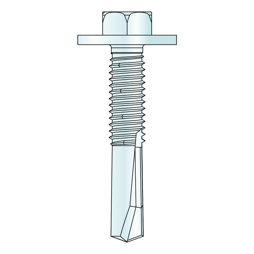
(1) X1S1214 Screws used to secure the upper stud to the connector
(2) XLSH34B1414 Screws used to secure the lower stud to the connector
(3) TTN25134H Concrete Screws used to secure the connector the concrete floor slab
(4) XLQ114B1224 Screws used to secure the connector the Steel Beam
Installation
Installation
Installation Sequence
1) Connect to Primary Structure
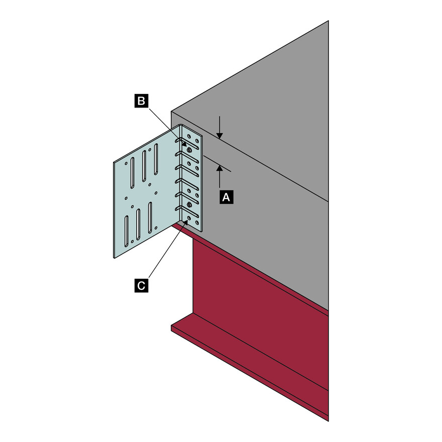
Secure connector to primary structure with specified fasteners (2 No. TNT through hexagonal holes for concrete support [B] or 8 No XLQ through round holes for steel support [C]) . When connecting to a concrete support a minimum fastener edge distance of 50mm is required [A]
2) Install Lower Stud
Secure lower stud with specified number of XLSH screws into the movement slots [D]. Screws are to be fixed centrally within the movement slots, allowing a vertical movement of the lower stud. A minimum end distance of 12.5mm is required [E].
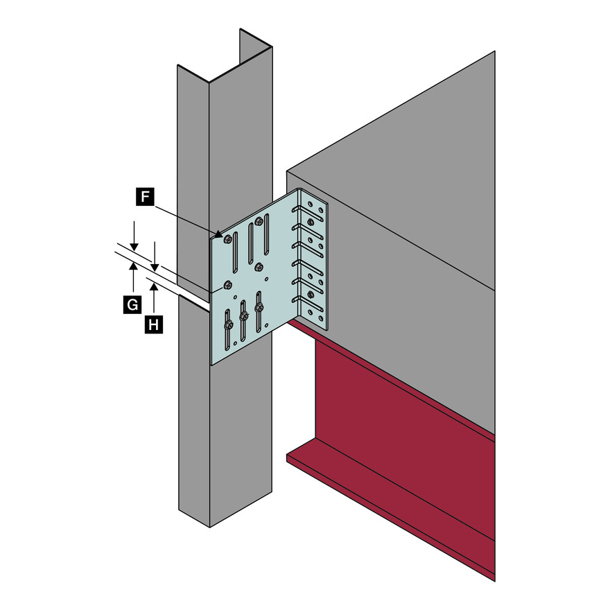
3) Install Upper Stud
Secure upper stud with specified number of X1S screws through the round holes [F], ensuring that the lower screws are a minimum of 12.5mm from the bottom end of steel stud [G]. Minimum gap between upper and lower studs is 12,5mm [H]
