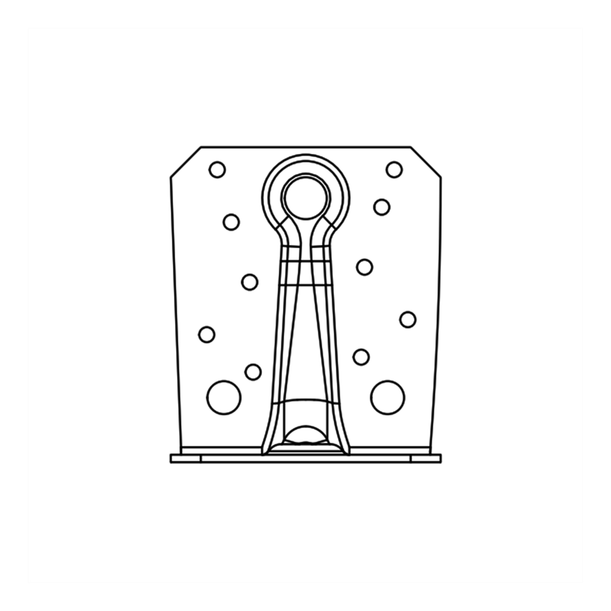
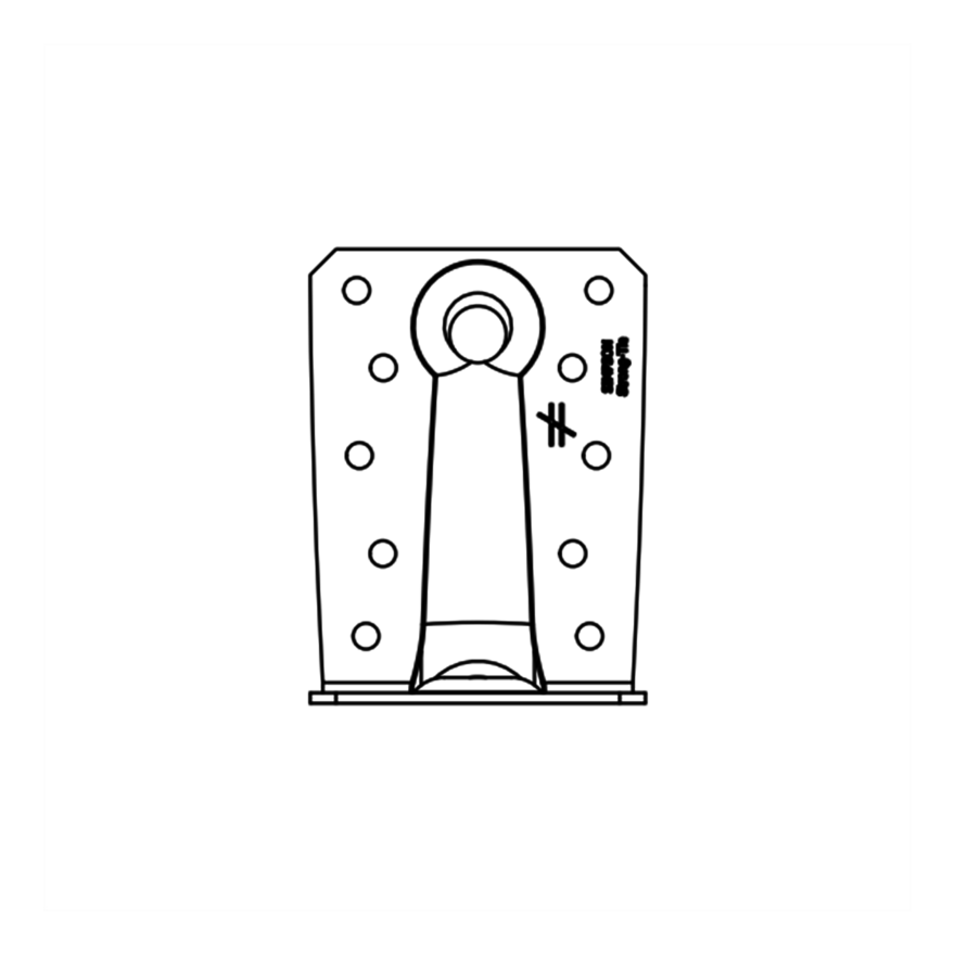
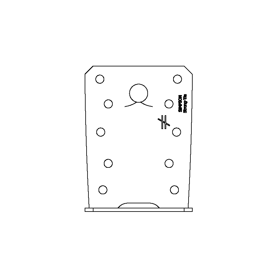
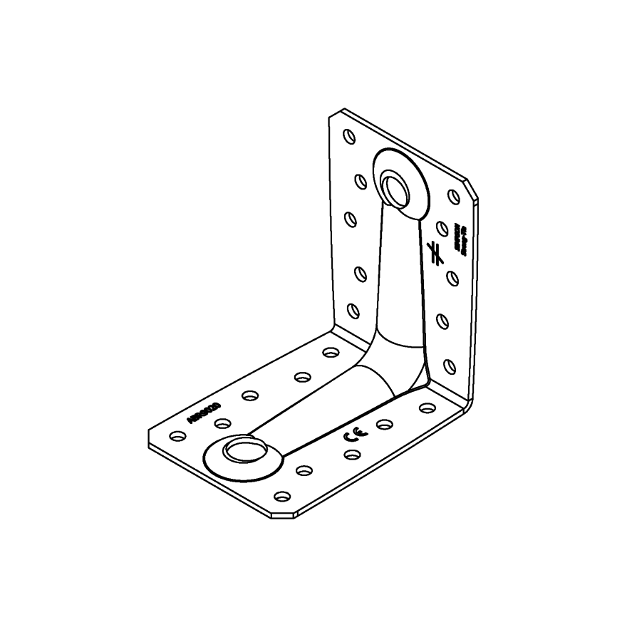
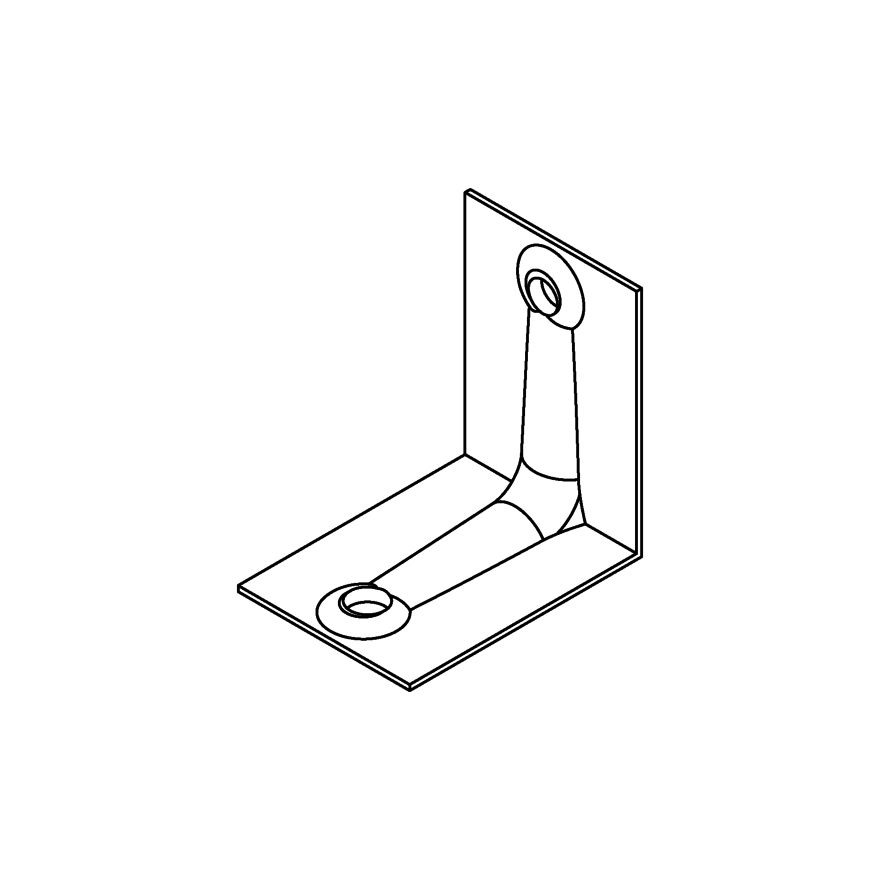
Reinforced Angle Bracket
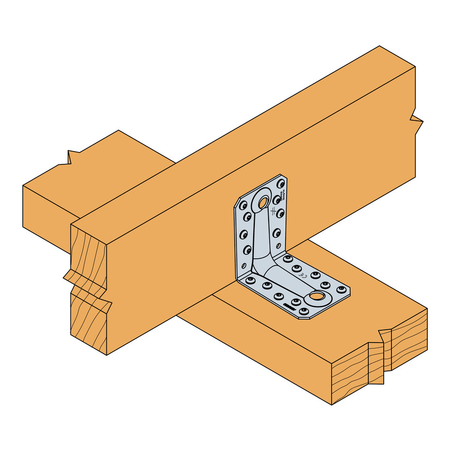
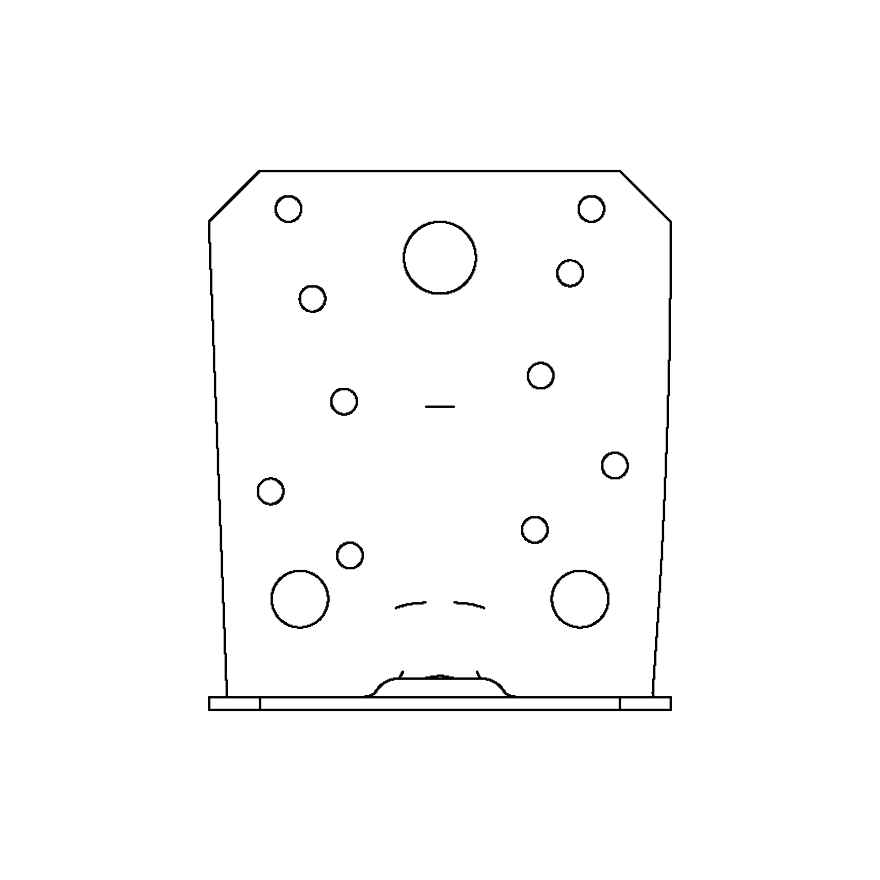
Reinforced angle brackets are suitable for structural applications in framing and timber framed houses as well as light gauge steel construction.
Product Details
Features
Material
- Galvanized steel S250GD + Z275 according to NF EN 10346.
Benefits
- Reinforcing ribs provide enhanced performance.
Application
Suitable On
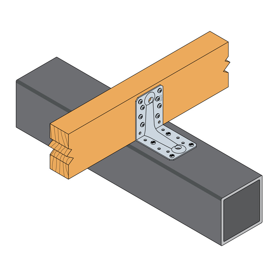
- Supporting member: solid wood, glued-laminated wood, concrete, steel, etc.
- Supported member: solid wood, composite lumber, glued-laminated wood, triangular trusses, profiles, etc.
When to Use
- Fastening of small trusses.
- Cladding plates, cladding uprights.
- Rafter anchors, cantilevers, headers, etc.
- Light gauge steel.
Technical Data
Product capacities - Timber to timber - Full nailing - 2 angles brackets
| References | Product capacities - Timber beam to timber beam - Full nailing - 2 angle brackets | |||||||||||||
|---|---|---|---|---|---|---|---|---|---|---|---|---|---|---|
| Number of Fasteners | Characteristic capacities - Timber C24 - 2 angle brackets per connection [kN] | |||||||||||||
| Joist | Flange B | R1.k | R2.k = R3.k | R4.k = R5.k* | ||||||||||
| Qty | Qty | CNA4.0x35 | CNA4.0x40 | CNA4.0x50 | CNA4.0x60 | CSA5.0x40 | CNA4.0x35 | CNA4.0x40 | CNA4.0x50 | CNA4.0x60 | CSA5.0x40 | CNA4.0x35 | CNA4.0x40 | |
| ABR7015 | 6 | 8 | 5.2 | 6.1 | - | - | - | 6.6 | 7.3 | - | - | - | 4,2 / kmod^0,3 | 4,8 / kmod^0,3 |
| ABR9020 | 8 | 10 | 9.7 | 10.8 | 11.9 | 14.9 | 14.6 | 9.4 | 10.3 | 12.2 | 13 | 12.3 | 4,6 / kmod^0,7 | 4,9 / kmod^0,7 |
| ABR10525 | 10 | 14 | 12.7 | 17.2 | 23.5 | 29.4 | - | 10.8 | 12.1 | 18.5 | 19.7 | - | 10,6 / kmod^0,2 | - |
* b = 75 mm and e = 130 mm
To obtain the resistance values for a single bracket, the values in the above table should be divided by two, provided that the supported beam is locked in rotation. Please consult our ETA-06/0106 if the beam is free to rotate.
Product capacities - Timber to timber - Partial nailing - 2 angles brackets
| References | Product capacities - Timber beam to timber beam - Partial nailing - 2 angle brackets | |||||||||
|---|---|---|---|---|---|---|---|---|---|---|
| Number of Fasteners | Characteristic capacities - Timber C24 - 2 angle brackets per connection [kN] | |||||||||
| Joist | Flange B | R1.k | R2.k = R3.k | |||||||
| Qty | Qty | CNA4.0x35 | CNA4.0x40 | CNA4.0x50 | CNA4.0x60 | CNA4.0x35 | CNA4.0x40 | CNA4.0x50 | CNA4.0x60 | |
| ABR9020 | 4 | 6 | 4.9 | 5.9 | 7.8 | 9.8 | 5.9 | 6.5 | 7.6 | 8.1 |
| ABR10525 | 6 | 6 | 4.8 | 5.7 | 7.6 | 9.5 | 9.7 | 10.6 | 13.4 | 14.3 |
To obtain the resistance values for a single bracket, the values in the above table should be divided by two, provided that the supported beam is locked in rotation. Please consult our ETA-06/0106 if the beam is free to rotate.
Product capacities - Timber column to timber beam - 2 angle brackets
| References | Product capacities - Timber column to timber beam - 2 angle brackets | |||||||
|---|---|---|---|---|---|---|---|---|
| Number of Fasteners | Characteristic capacities - Timber C24 - 2 angle brackets per connection [kN] | |||||||
| Joist | Flange B | R1.k | R2.k = R3.k | |||||
| Qty | Qty | CNA4.0x40 | CNA4.0x60 | CSA5.0x40 | CNA4.0x40 | CNA4.0x60 | CSA5.0x40 | |
| ABR9020 | 4 | 6 | 6 | 9.8 | 11.8 | 5.1 | 6.9 | 7.1 |
| ABR10525 | 6 | 8 | 9.4 | 14.8 | 25.5 | 10.2 | 13.9 | 14.2 |
Product capacities - Timber beam to steel 6 mm - Partial nailing - 2 angles brackets
| References | Product capacities - Timber beam to steel beam 6 mm - Partial nailing - 2 angle brackets | ||||
|---|---|---|---|---|---|
| Number of Fasteners | Characteristic capacities - Timber C24 - 2 angle brackets per connection [kN] | ||||
| Joist | Flange B | R1.k | |||
| Qty | Type | Qty | Type | CNA4.0x60 | |
| ABR9020 | 8 | CNA | 4 | PDPA-75 | 12.1 |
| ABR10525 | 10 | CNA | 4 | PDPA-75 | 15.3 |
Installation
Installation
Fixing
On wood:
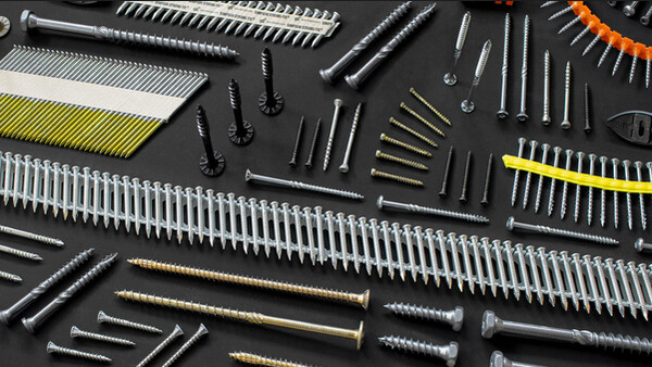
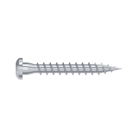
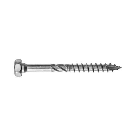
- CNA annular ring-shank nails dia. 4.0 x 35 or dia. 4.0 x 50 mm.
- CSA screws dia. 5.0 x 35 mm or CSA screws dia. 5.0 x 40 mm.
- Bolts.
- LAG screws.
On concrete:
Concrete substrate
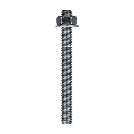
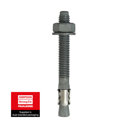
- Mechanical anchor: WA M10-78/5 OR WA M12-104/5 pin.
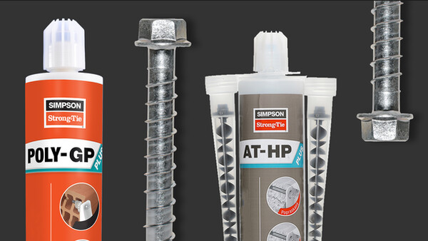
- Chemical anchor: AT-HP resin + LMAS M10-120/25 or LMAS M12-150/35 threaded rod.
Hollow masonry substrate:
- Chemical anchor: AT-HP or POLY-GP resin + LMAS M12-150/35 threaded rod + SH M16-130 screen.
On steel:
- Bolts.
Technical Notes
Technical Notes
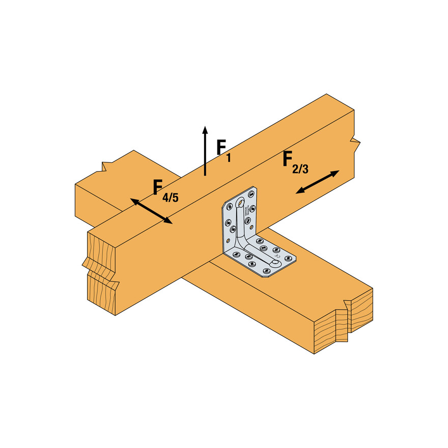
F1: tensile force in the central axis of the angle-bracket
Particular situation of a fastening with only one angle-bracket:
- If the overall structure prevents the rotation of the purlin or the post, the tensile strength is equal to half of the given value for two angle-brackets.
- Otherwise, the connection resistance depends on the « f » distance between the vertical contact surface and the point of load application.
F2 and F3: shear lateral force
Particular situation of a connection with only one angle-bracket:
- The resistance value to consider is equal to half of the one given for two angle-brackets.
F4 and F5: transversal force directed towards or opposite the angle-bracket
- The connection resistance depends on the « e » distance between the base of the angle-bracket and the point of load application.
- To consult corresponding loads, contact us.
Only F1, F2 and F3 forces for connections with 2 angle-brackets are present on this sheet.
For more information, contact us.
