ER
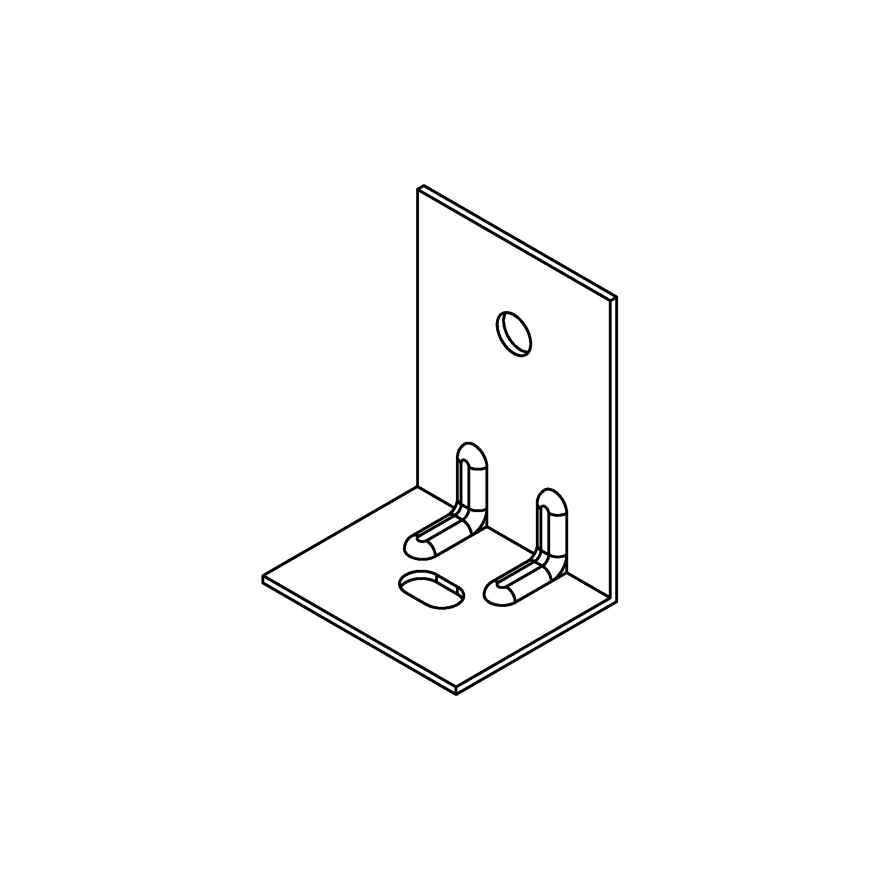
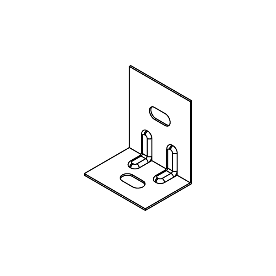
Reinforced Angle Bracket
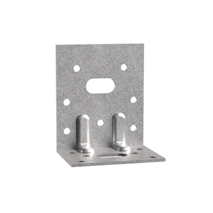
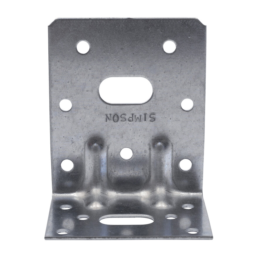
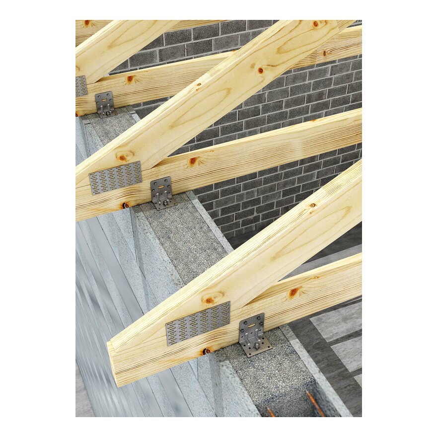
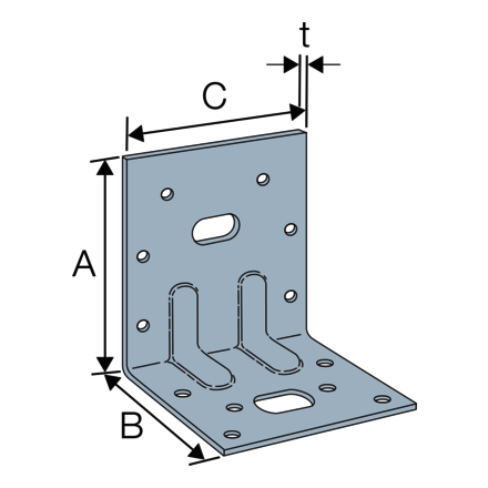
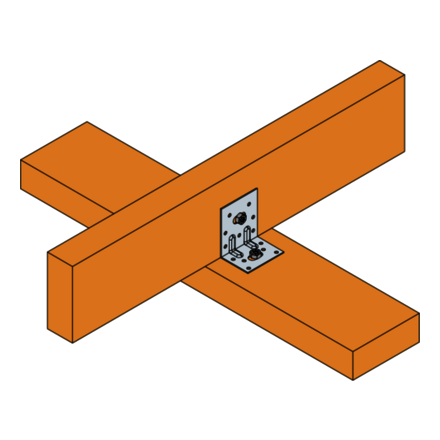
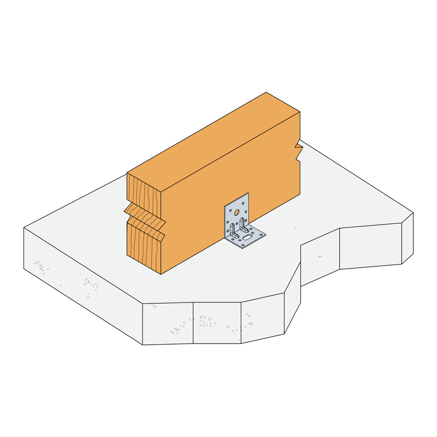
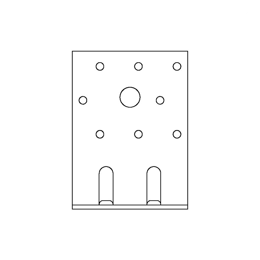
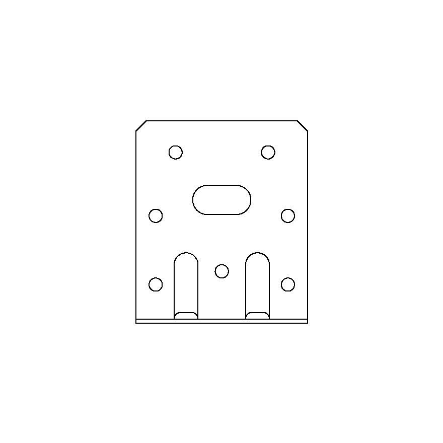
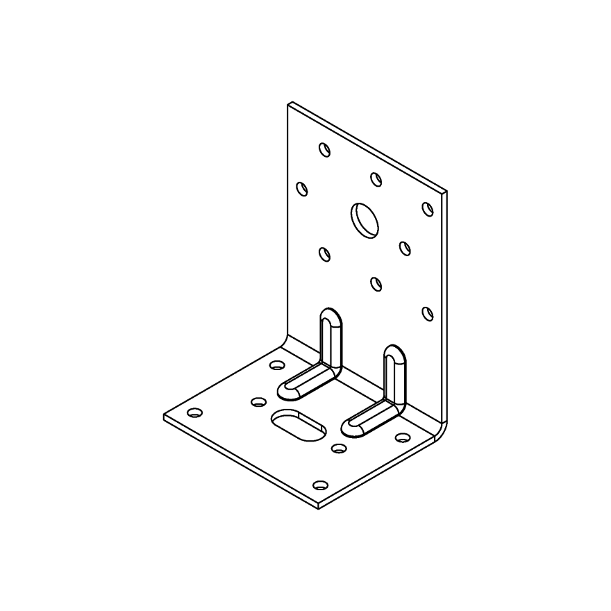
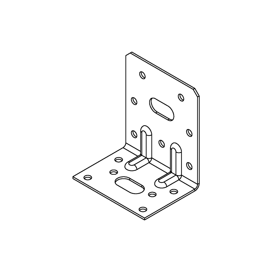
Reinforced angle brackets are suitable for structural applications in framing and wood-frame houses.
CE Marking
ETA
Service class 2
Indoor
Electrogalvanized steel Z275
Product Details
Features
Material
- Galvanized steel S250GD + Z275 according to NF EN 10346.
Application
Header member
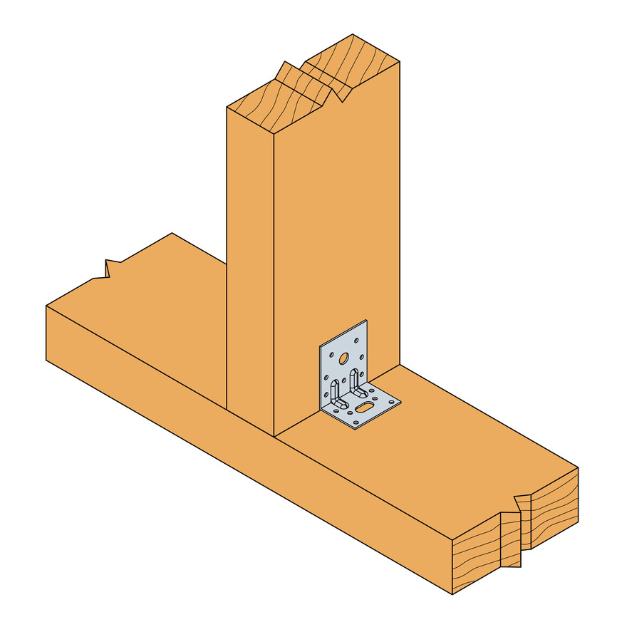
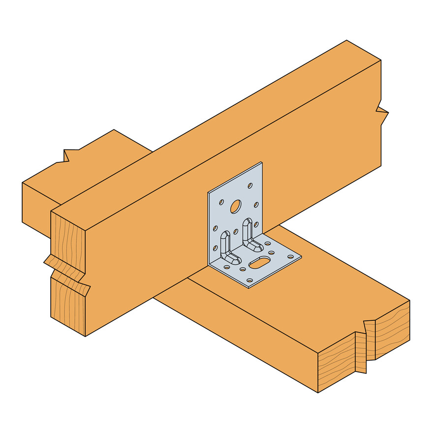
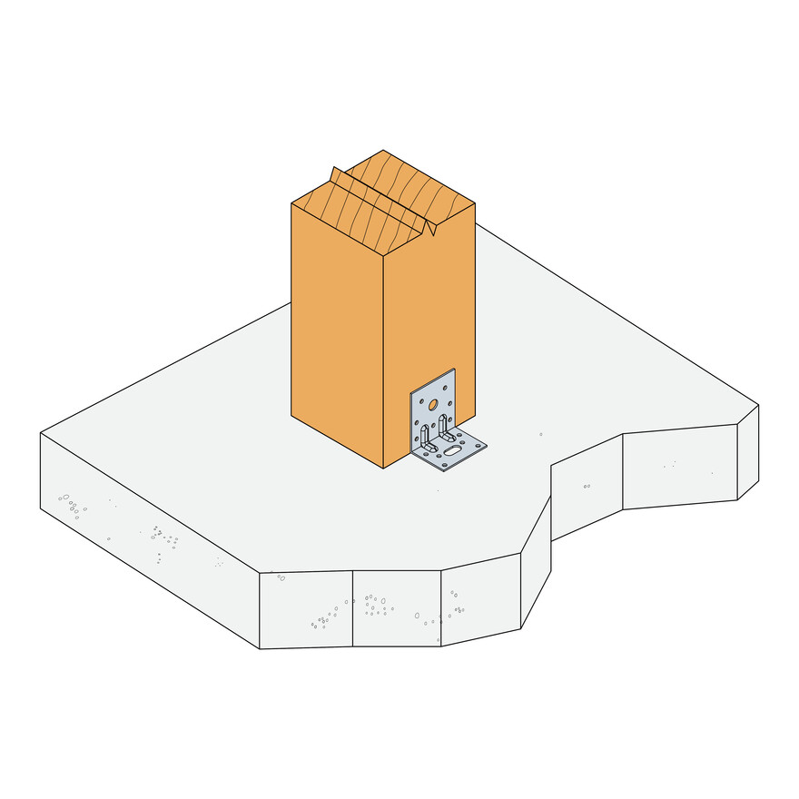
- Supporting member: solid wood, glued-laminated wood, concrete, steel, etc.
- Supported member: solid wood, composite lumber, glued-laminated wood, triangular trusses, profiles, etc.
For Use With
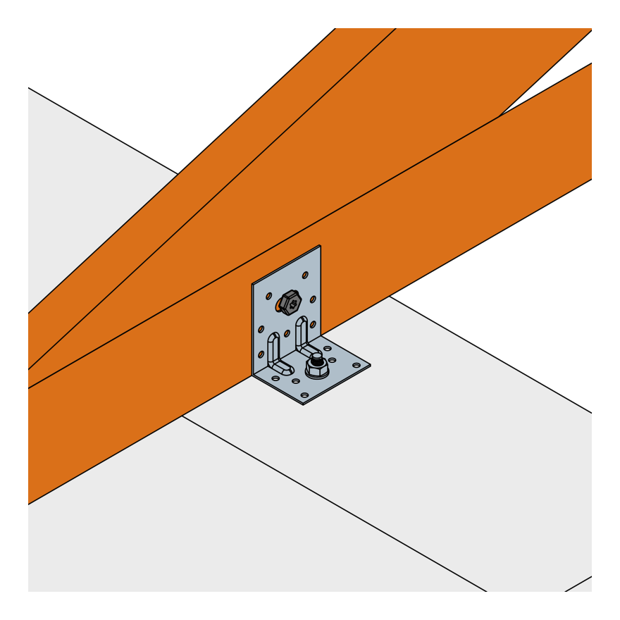
- Fastening of small trusses.
- Cladding plates, cladding uprights.
- Rafter anchors, cantilevers, headers, etc.
Installation
Installation
Fixing
On wood:
- CNA annular ring-shank nails dia. 4.0 x 35 or dia. 4.0 x 50 mm.
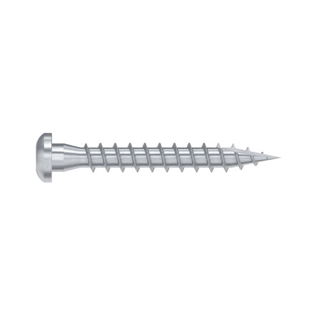
- CSA screws dia. 5.0 x 35 mm or CSA screws dia. 5.0 x 40 mm.
- Bolts.
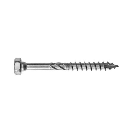
- LAG screws.
On concrete:
Concrete substrate
- Mechanical anchor: WA M10-78/5 OR WA M12-104/5 pin.
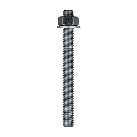
- Chemical anchor: AT-HP resin + LMAS M10-120/25 or LMAS M12-150/35 threaded rod.
Hollow masonry substrate:
- Chemical anchor: AT-HP or POLY-GP resin + LMAS M12-150/35 threaded rod + SH M16-130 screen.
On steel:
- Bolts.
Installation
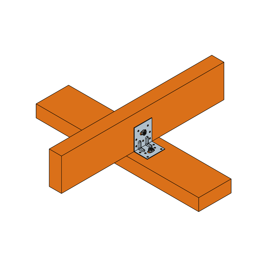
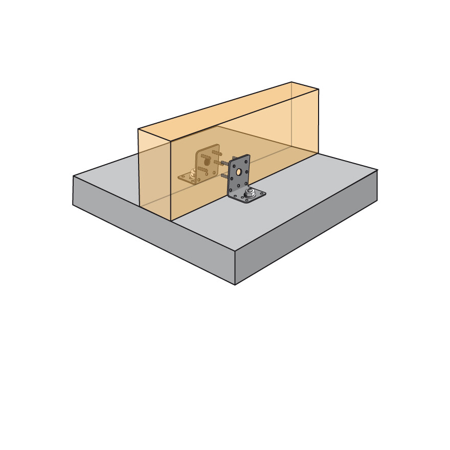
- Come with the joist,
- Add nails. It can be also screwed,
- If the header is made out of timber, the angle bracket can be attached to it with nails or screw,
- If the header is made out of concrete, the angle bracket must be attached with adapted anchors (using the installation data from the anchor)
Technical Notes
Informations
F1: tensile force in the central axis of the angle-bracket
Particular situation of a fastening with only one angle-bracket:
- If the overall structure prevents the rotation of the purlin or the post, the tensile strength is equal to half of the given value for two angle-brackets.
- Otherwise, the connection resistance depends on the « f » distance between the vertical contact surface and the point of load application.
F2 and F3: shear lateral force
Particular situation of a connection with only one angle-bracket:
- The resistance value to consider is equal to half of the one given for two angle-brackets.
F4 and F5: transversal force directed towards or opposite the angle-bracket
- The connection resistance depends on the « e » distance between the base of the angle-bracket and the point of load application.
- To consult corresponding loads, contact us.
Only F1, F2 and F3 forces for connections with 2 angle-brackets are present on this sheet.
For more information, contact us.
Certification
Declaration of Performance (DoP)
it-dop-e06-0106-10.pdf
(145.95 KB)
it-dop-e06-0106-issue-8.pdf
(98.3 KB)
it-dop-e06-0106-issue-7.pdf
(101.8 KB)
it-dop-e06-0106-issue-6.pdf
(42.44 KB)
it-dop-e06-0106-issue-5.pdf
(27.91 KB)
162d98bc9ac5a9766c8d7ba59b54de21961b969d.pdf
(24.76 KB)
it-dop-e06-0106-issue-3.pdf
(34.84 KB)
it-dop-e06-0106-issue-2.pdf
(34.71 KB)
it-dop-e06-0106-issue-1.pdf
(32.43 KB)
uk-dop-e06-0106-10.pdf
(139.61 KB)
uk-dop-e06-0106-issue-9.pdf
(99.15 KB)
uk-dop-e06-0106-issue-8.pdf
(99.04 KB)
uk-dop-e06-0106-issue-7.pdf
(99.61 KB)
uk-dop-e06-0106-issue-6.pdf
(42.29 KB)
uk-dop-e06-0106-issue-5.pdf
(27.77 KB)
b3e3ef5e5492847232064e535a060b5bad7c05f4.pdf
(34.53 KB)
df170b9bc1e51f91e61521449f22ab2e0dd9d847.pdf
(34.35 KB)
European Technical Assessment (ETA)
eta-06-0106-2021-04-09.pdf
(11.66 MB)
eta-06-0106-2020-01-29-cor1.pdf
(13.43 MB)
eta-06-0106.pdf
(13.43 MB)
eta-060106-sst-ab-r10-2018-issued.pdf
(10.1 MB)
eta-060106-sst-ab-v8-2016.pdf
(9.59 MB)
